

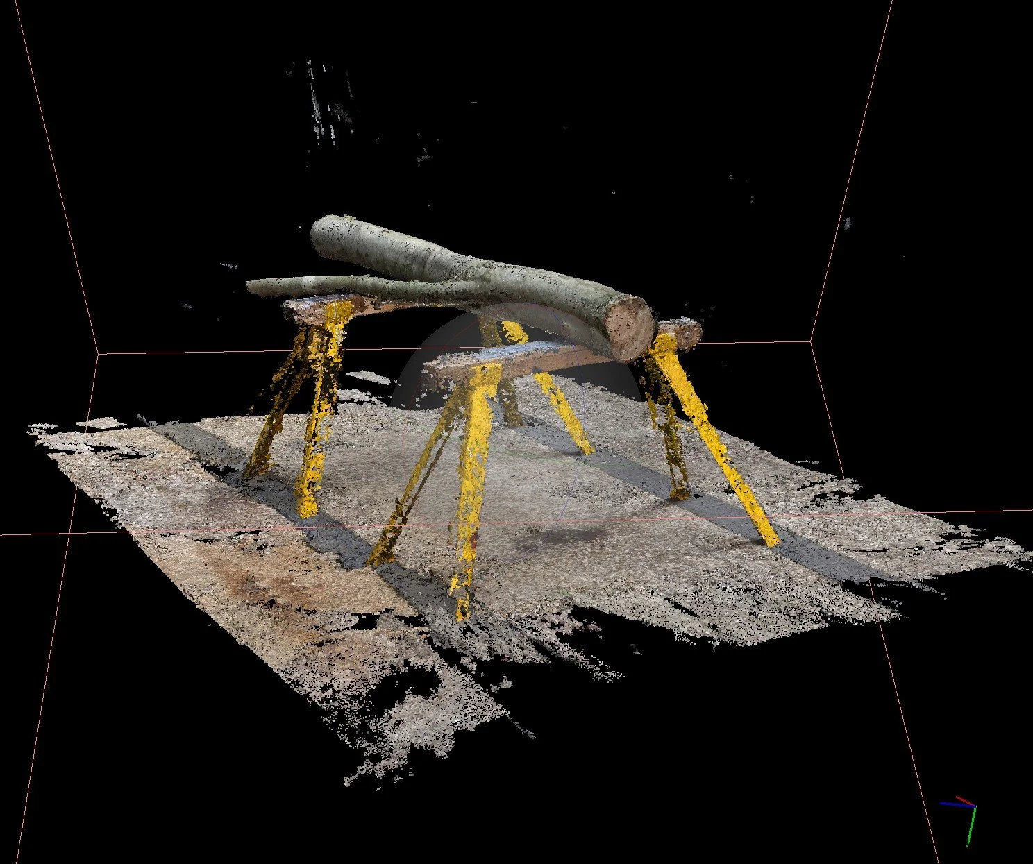
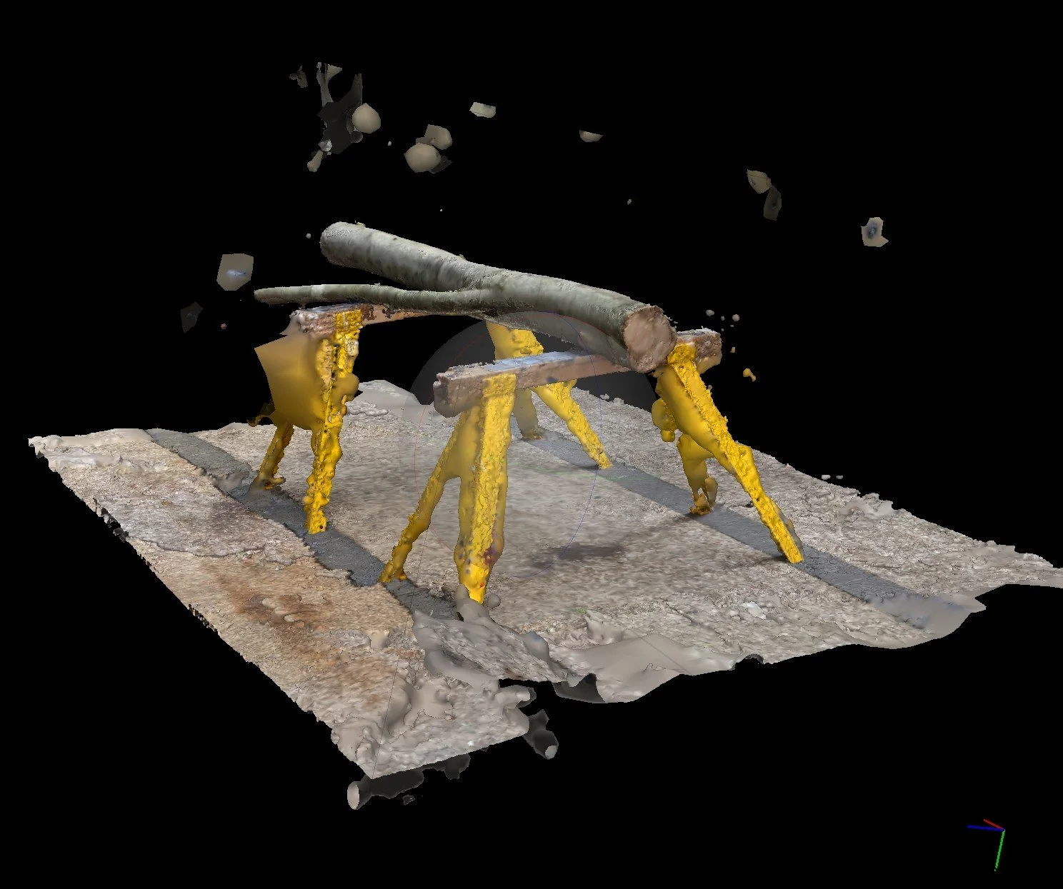
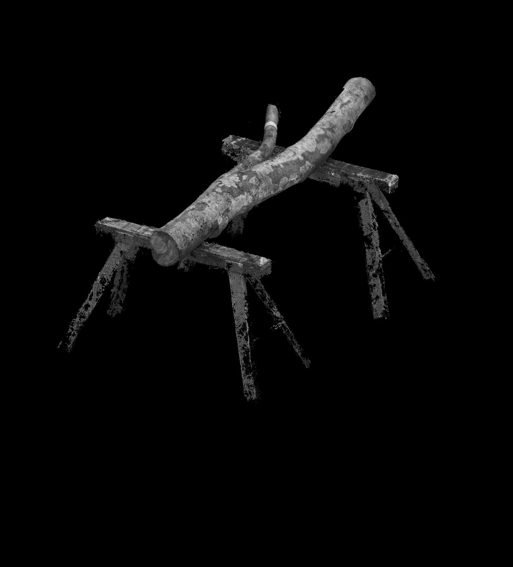
Using the aligned photos, a diffuse set of points is created. From this Agisoft then builds a proper pointcloud. This can then be exported into programs such as Cloudcompare for better visualisations. From the pointcloud, a mesh is then constructed. In either this step or the previous, the model can be trimmed leaving only the desired object. A key step in this process is scaling of the object. Using measurements taken physically, these points are located on the digital model and scaled accordingly.
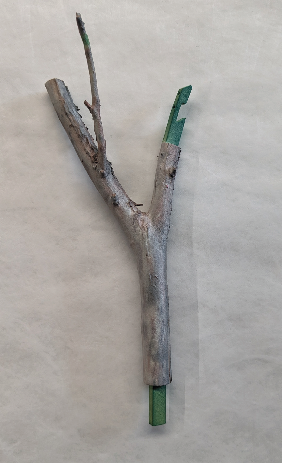
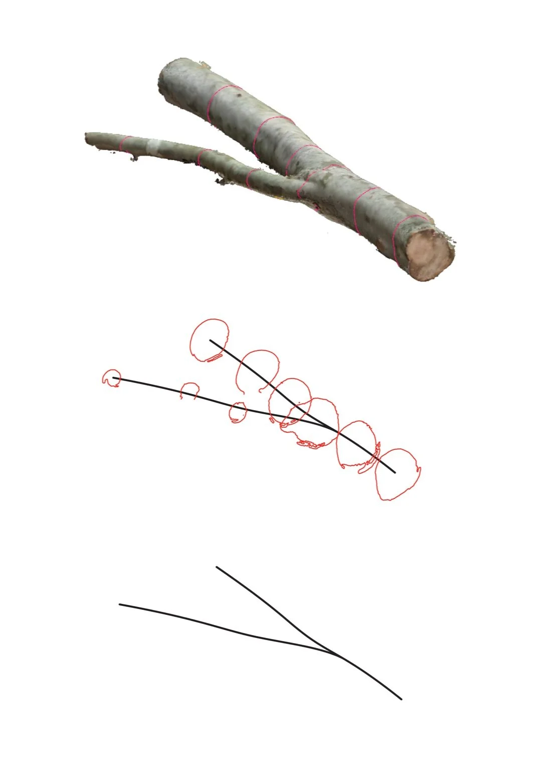
The final mesh was then able to be exported into rhino where its geometry could be further analysed and documented. For the branch pictured right, contours were produced that demonstrated its relative thickness. From these contours, the centroids of each were found. This then allowed a spline to be drawn through the centroid points that reduced the branch down to its most simple geometrical form. This technique was used in future assignments to reduce file sizes and complexity when finding optimal arrangements of branches in a speculative structure.
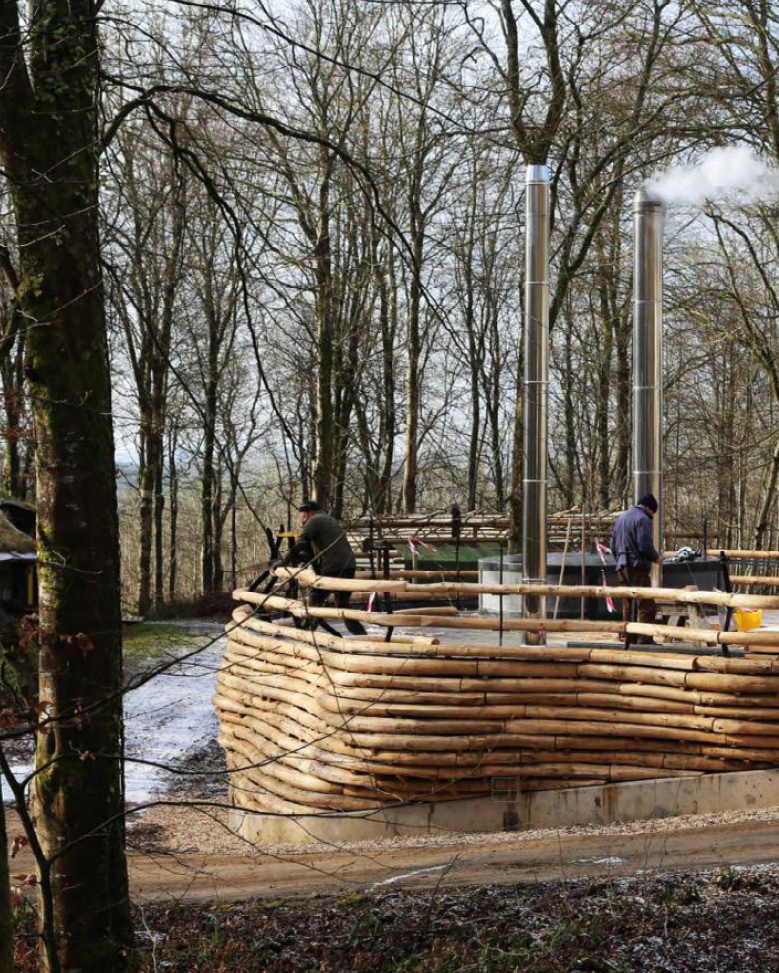
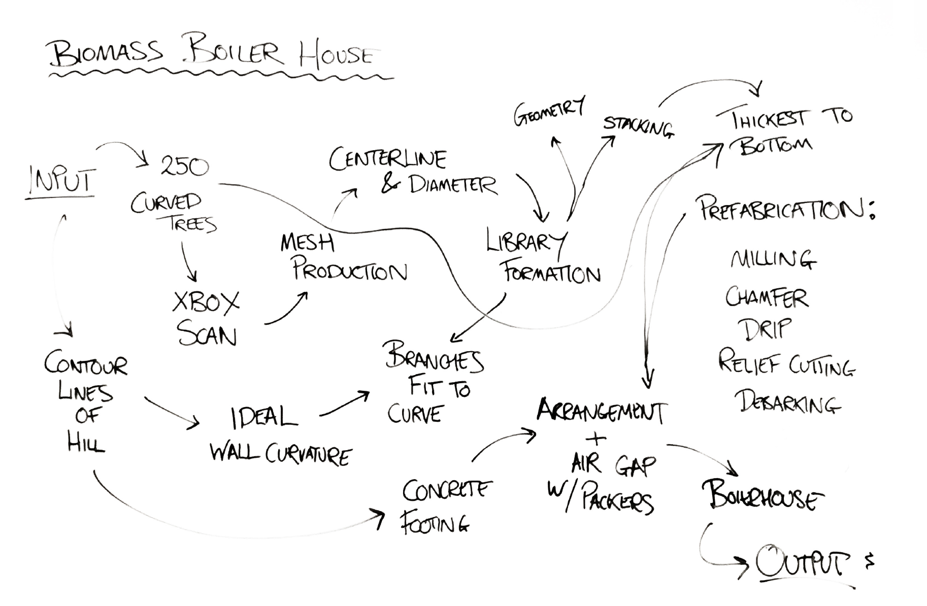
Assignment 2 - Digital to Physical - began by examining various precedents to understand the workflows and logistics of delivering a project using small diameter timbers. One such precedent was Hooke Park - Biomass Boiler House.
The students involved in the project began by 3D scanning 250 naturally curved douglas fir trees, then taking the centreline and diameter information from the resultant meshes. This data was then used to fit the trunks to an undulating surface that would form the envelope of the building. The smooth continuous curves of the ‘walls’ of this structure were designed to reflect the topology of the site and contribute to the robustness of the envelope itself. By closely inspecting the design and fabrication methodology, we were able to get a better insight into how our own project may come together.
The fabrication part of this precedent was especially interesting, seeing how the logs were prepared and then ultimately assembled. A modified bandsaw was fabricated that allowed for angled cutting and rotation around the logs. Cuts were performed on the top and bottom of the logs to ensure stability when stacking, and a chamfer was also cut, angled away from the structure to disperse rain water. Oak packers were placed every 600 mm along a course of logs to create an air gap of 15mm between members. This ensured that the logs could be well ventilated and remain dry, slowing their deterioration in the relatively wet climate of South West England. Examining this project then helped us create a flowchart for the design and manufacture of our own timber seasoning shelter.
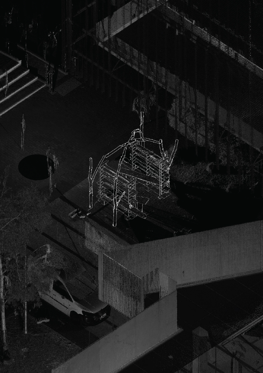
Assignment 3 saw us divided into different groups again, each with a different focus. Our group was responsible for the design and construction of a ‘branch network’ that would span the two wall sections. Within our groups, we were assigned different responsibilities with my self being tasked with the computational design aspect of the final structure.
This primarily involved developing a grasshopper script that could generate a structure from our inventory of branches and was flexible enough to produce different forms depending on the number of branches to be used.
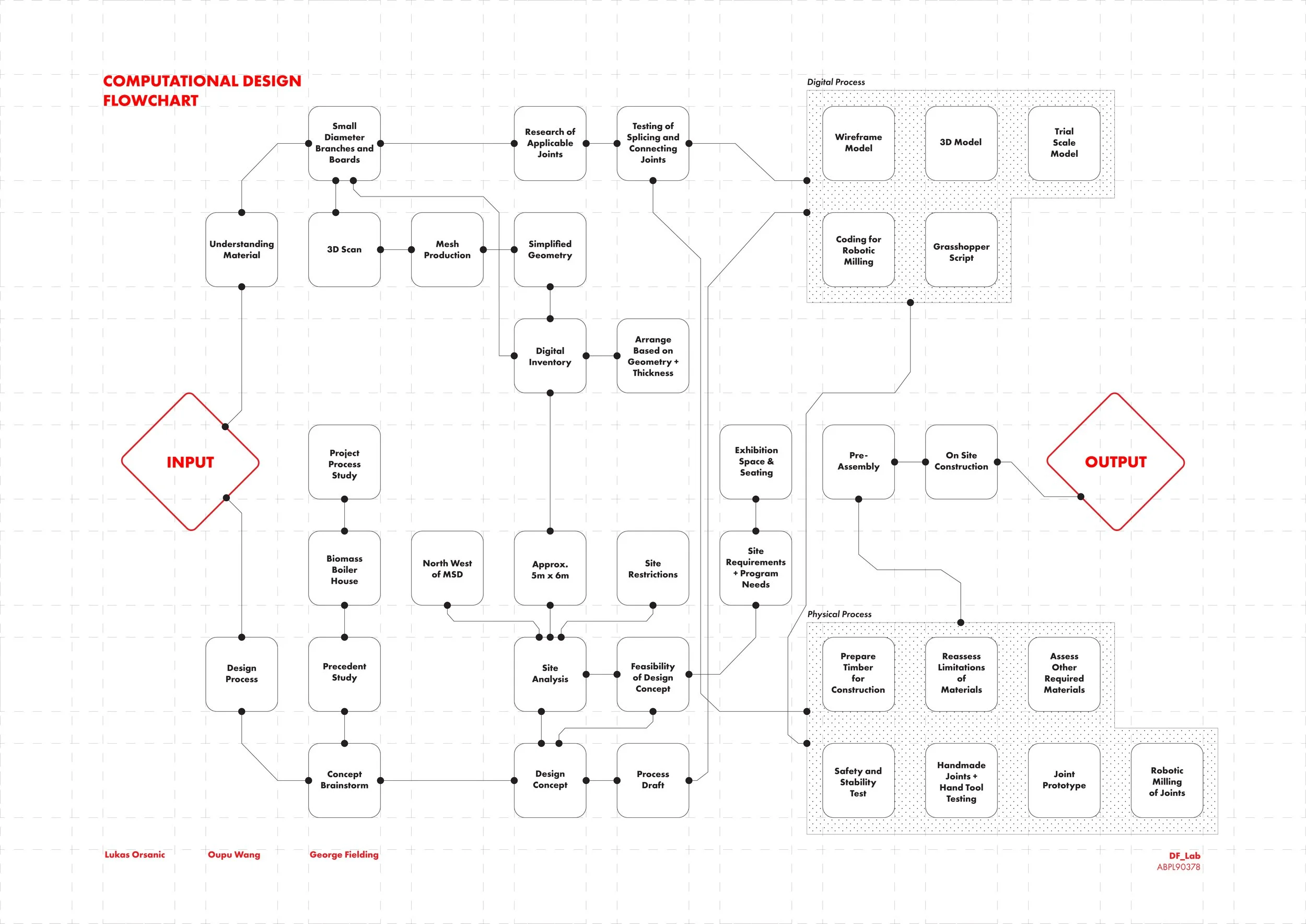
Timber Seasoning Shelter
Timber Seasoning Shelter
As well as creating 1:1 prototypes, branch connections at 1:10 scale were also investigated. Using the same joinery methods, we looked to explore how successful they would be if they were cut from our branches. Initially, and rather embarrassingly, I fully misunderstood the logic of this and supplied files that were essentially the branches with imaginary joints tacked on to them. Upon realising that these joints of course had to be cut from the branch, the joints could only exist if they could be contained within the volume of the trunk. This mistake was rectified and the 1:10 branch prototypes were successfully 3D printed.
Assignment 1: Material Acquisition, introduced photogrammetry and the necessary workflows to produce highly detailed digital replications of physical objects. For the purposes of this subject, those objects would be branches and slabs of wood sourced from a tree felled earlier in the year.
Learning the necessary skills in photogrammetry would prove highly useful in ultimately designing and constructing with these irregular timbers. Knowing their specific geometries and having a digital replication of them, increases the ease by which they can be utilised in a prospective project and can serve as an example of highly resource efficient, sustainable construction
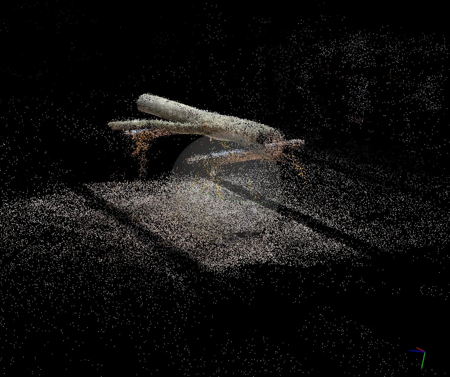
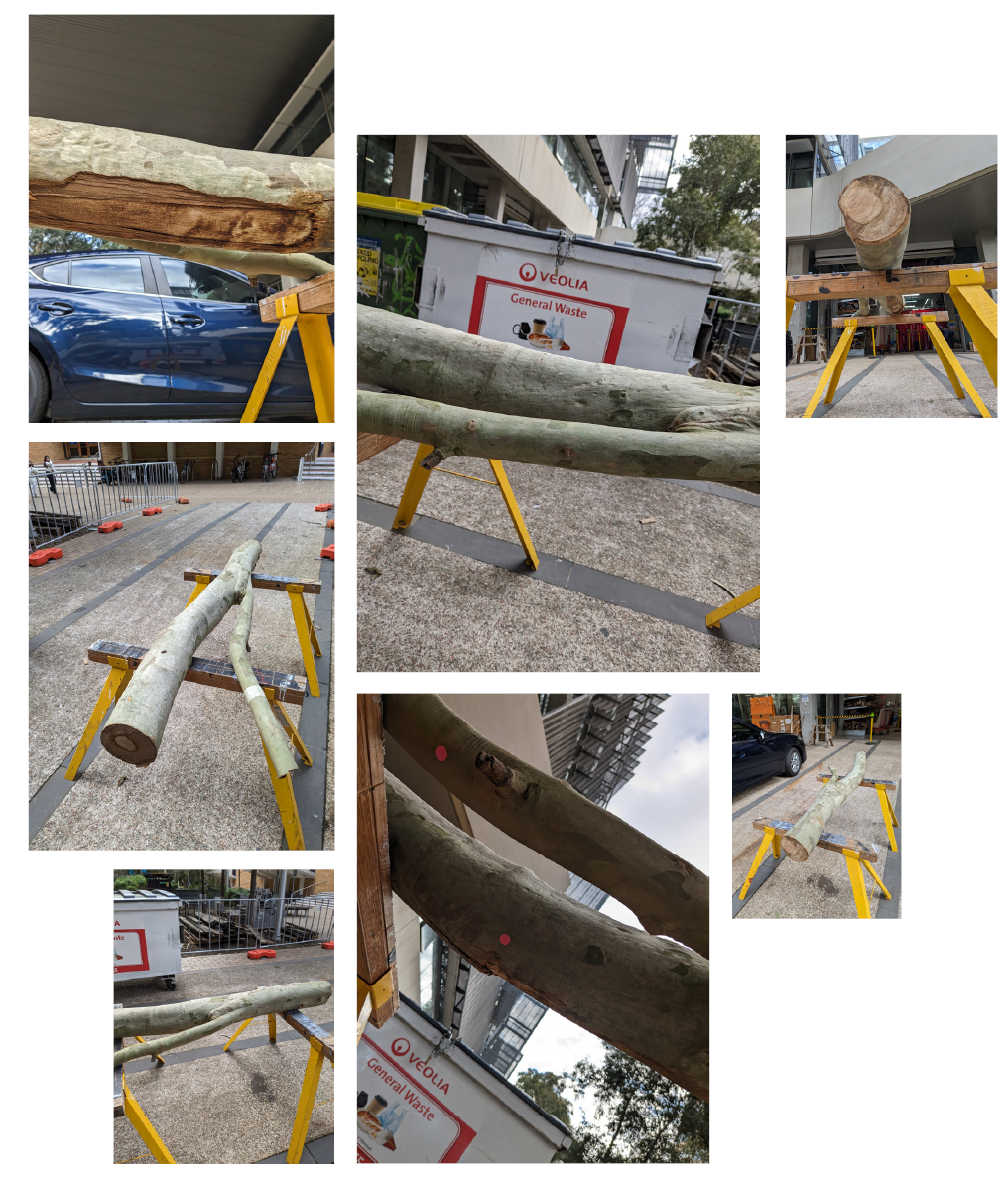
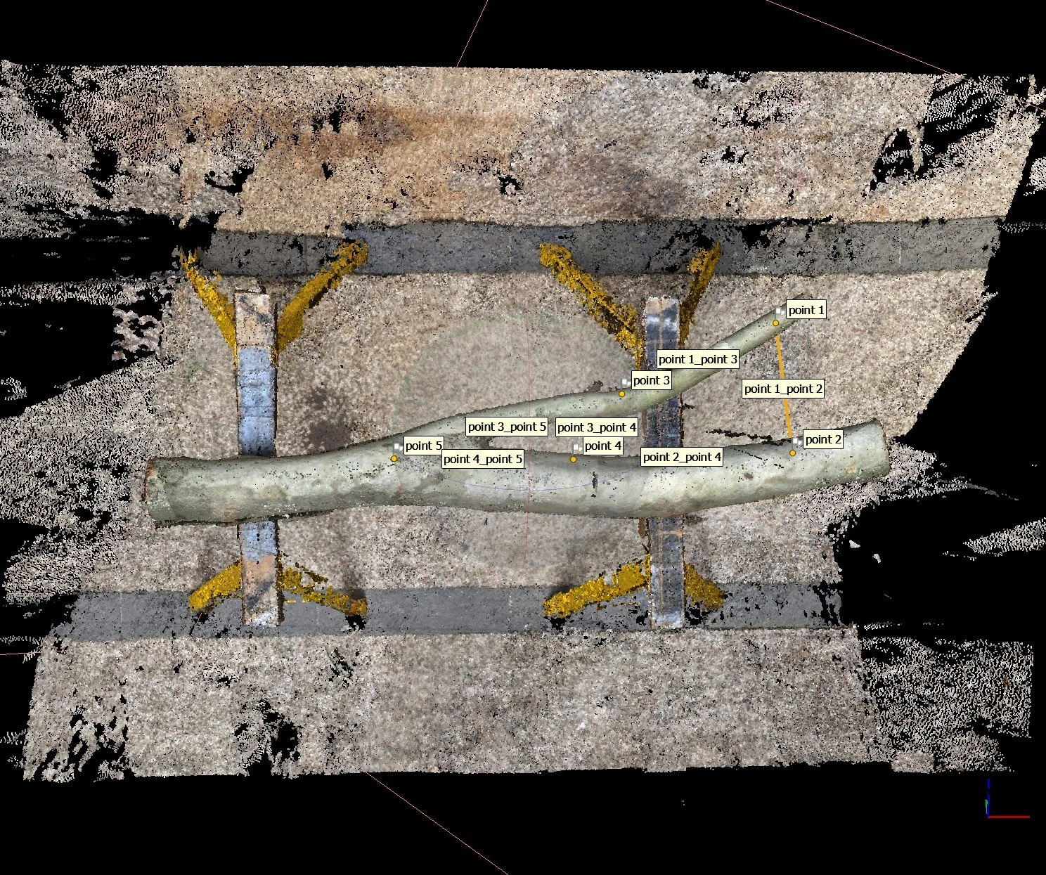
Pictured here are some of the images captured that were used in creating the branch mesh. In total, 138 images were taken of the branch taking care to capture every part of it, and if possible from various angles. This process had to be done twice due to a few errors that made themselves evident when constructing the pointcloud.
These images were taken on a pixel 6a smartphone and not a more suitable ‘point and shoot’ camera and so, idiosyncrasies from the phone camera gave relatively undesirable results. One of these is the auto-rotate feature of the phone, meaning that images had trouble aligning with Agisoft. Another complexity was that the phone automatically changes its focal length, and so, parts of the resulting pointcloud appeared to in places be floating above where they should actually be.
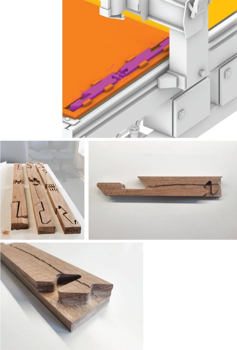
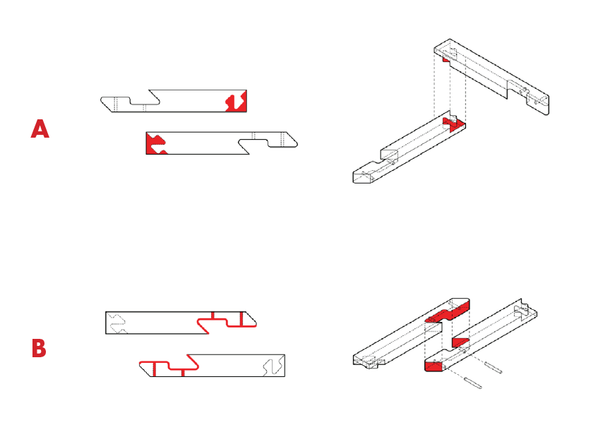
In addition to understanding the workflows, it was very important to understand the capabilities and limitations of the tools we had at our disposal. Using the learnings from the previous assignment regarding joinery, we were tasked with creating joints that could be milled on a CNC machine. Our group produced two joints - joint A is a connecting joint that fixes two members at 90 degrees using a modified dovetail connection. Joint B is a splicing connection that incorporates dowels.
From this process we learnt a lot about the CNC workflows but also the limitations of our joint design. Joint A despite working digitally, did not seem to work when physically reproduced. Joint B was more successful but required more post processing to remove artifacts produced during the milling process.
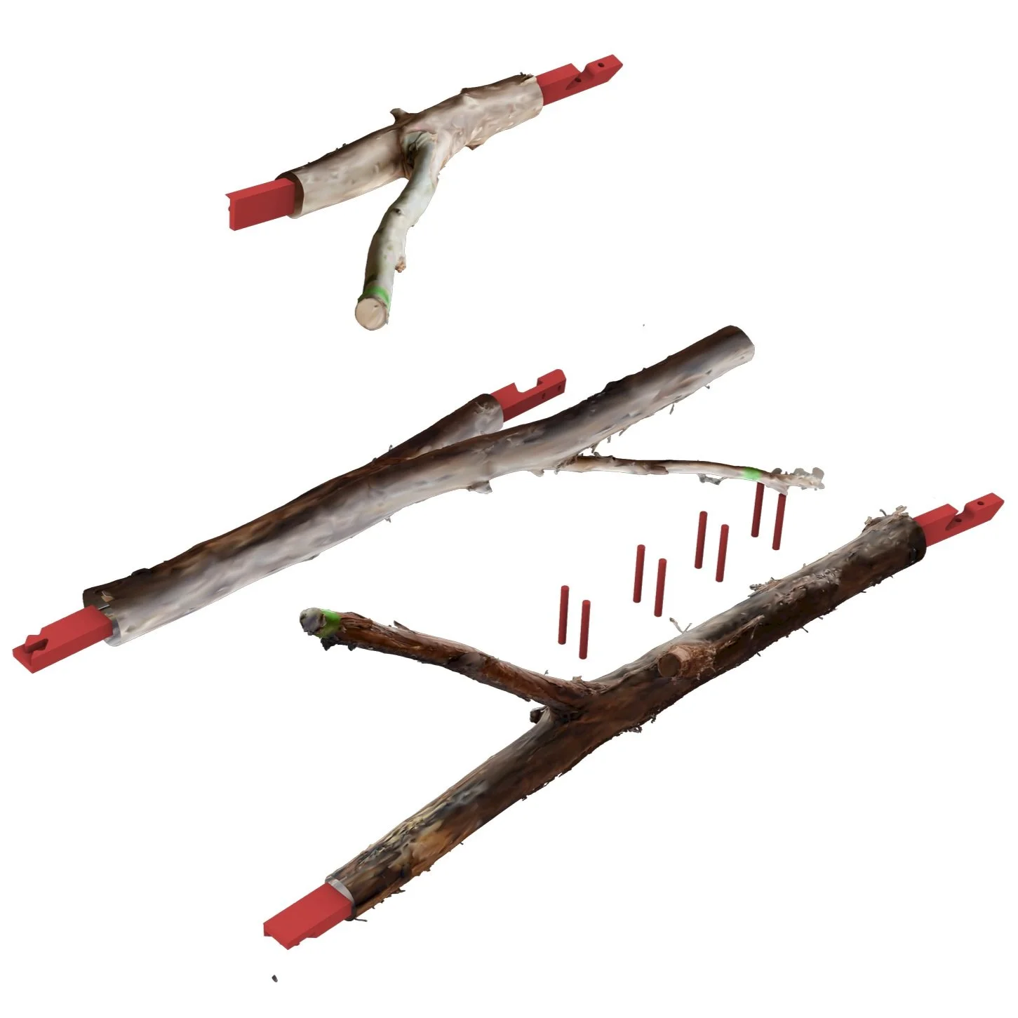
In order to cut the dowel holes for joint B we looked to use the 6-axis ABB robotic arm available in the robotics lab. Using a jig specifically manufactured for this purpose the timber was secured down in exactly the same position as in the digital file which was used to create the toolpaths.

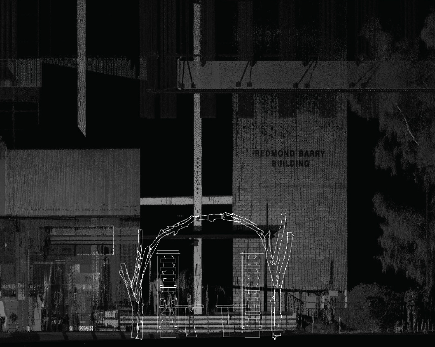
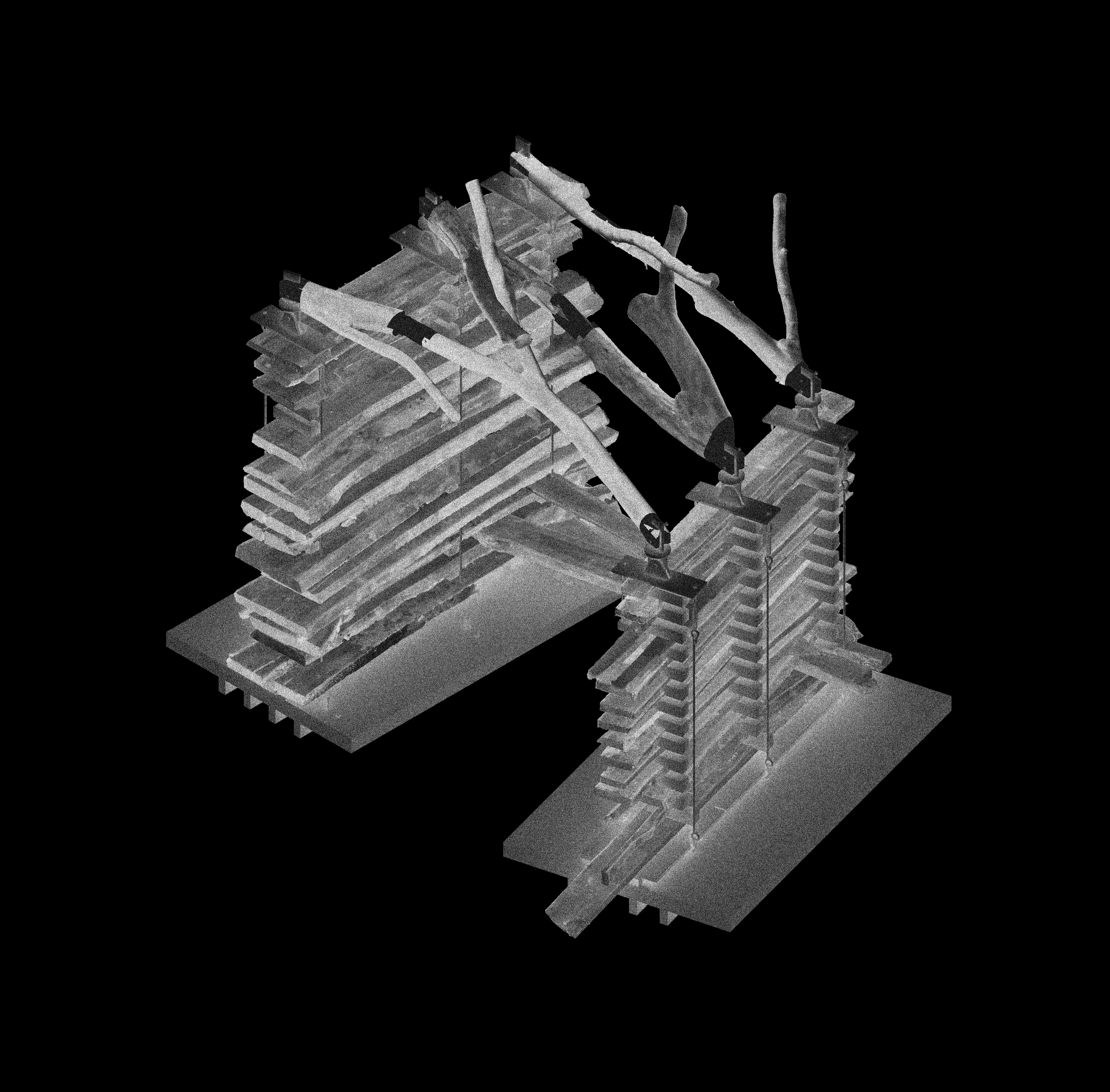
We ultimately proposed a design that used a wall system similar to that used in Peter Zumthor’s Swiss Sound Pavilion. The boards are kept separated by spacers, with the whole system being compressed both to allow the slabs to dry straight and provide the wall with rigidity. A number of boards are rotated out into the middle of the structure and supported by a number of short branch lengths. Branches also formed a sort of roof ‘dome’ that may allow the connection of a fabric to provide shade inside the structure. An immediate drawback to this design however is the fact that it did not keep whole branches intact, instead chopping them up for use in various elements and preventing a full showcase of their capability.

Assignment 3 saw us divided into different groups again, each with a different focus. Our group was responsible for the design and construction of a ‘branch network’ that would span the two wall sections. Within our groups, we were assigned different responsibilities with my self being tasked with the computational design aspect of the final structure.
This primarily involved developing a grasshopper script that could generate a structure from our inventory of branches and was flexible enough to produce different forms depending on the number of branches to be used.